


One of the important elements of sleep hygiene is to fit in with the hours of its duration in the peri-day cycle of the sun – fall asleep when it is dark, wake up with the sunrise. Unfortunately, nowadays artificial lighting is able to strongly disturb this state of equilibrium. The lantern that leads us with all the splendor falling directly into the window of our bedroom makes us forget about the comfortable darkness. Therefore, blinds were invented, which help to restore comfortable conditions conducive to falling asleep. However, they cause (at least for me) a problem with access to the waking rays of the sun in the morning. Hence, in my head, the idea of a device was born that would automate the process of opening and closing blinds at certain times. After a short reaserch, I found a DIY project of such a driver created by James cabuu.com
Its creation requires the composition of a dozen elements:
- printed elements

- printed circuit board created by James
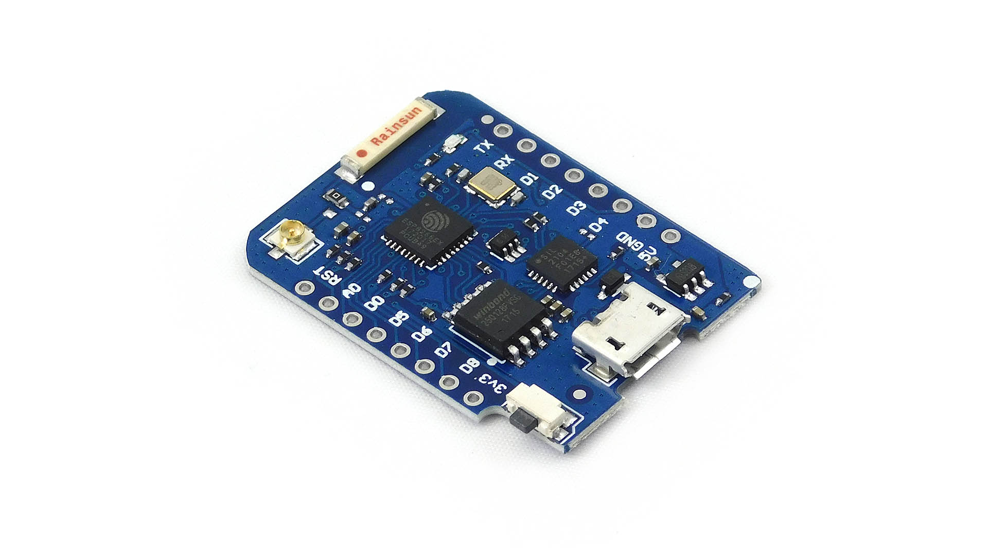
- D1 Mini microcontroller
- power module for D1 Mini

- L298N – dual channel motor controller

- motor with worm gear and DC encoder 12V

- LED WS2812B

- two buttons with overlays

- two resistors 10k Ohm

- 9V DC power supply

- additionally, some cable and goldpins


After complicating all the necessary elements, you can start the assembly:
- Solder the slots to the plate in the right places. There should be two 4×2 and 2×8 pin female and 1×6 pin male sockets. At your discretion, you can solder the engine directly to the plate.

- Place and solder 2 buttons in the marked places. Then solder the 2x10k Ohm resistors at RUP and RDOWN positions.

- Carefully solder the 3 cables at the ends of the WS2182B LED input and into the appropriate places on the plate. 5V, signal and GND correspond successively to the L, E and D signatures on the plate.

- Solder the 3 two-pin male sockets to the L298N motor controller at + – IN1 IN2 MOTORA as indicated on the controller plate.

- Solder the extended pin slots to the D1 Mini microcontroller and power module.

- Fold the whole thing, connect the power supply and micro usb cable to the computer. You can now upload the software using the Arduino IDE.

A short video of the project process is shown below:
